Our Solutions · Orthosis Lab
Custom orthosis and robotics lab
Custom shells from a scan or photographs, motorised off-the-shelf braces, and a robotic device for controlled post-operative motion. Five projects, with 3D previews you can explore in the browser.
Shared pipeline
From scan to print, a measurable gate at every step
Robotics
Robotic Rehabilitation — controlled motion at home
A robotic rehabilitation device that aims to bring early, controlled post-operative motion into the home. The clinical frame (range of motion, speed, torque layers) was set by physician decision; drive, power and safety chain were cross-reviewed by three separate AI systems. Its own page carries an interactive 3D preview.
Orthosis from photographs
Wrist splint — a custom shell from phone photographs
A volar wrist splint whose forearm–wrist geometry is captured from phone photographs, with skin offset and a biomimetic ventilation pattern. The capture protocol checks photo sufficiency up front; the shell does not go to print before passing watertightness, thickness and skin-gap gates. The first prototype was printed in carbon-reinforced nylon and trialled; strap placement and thickness are under revision.
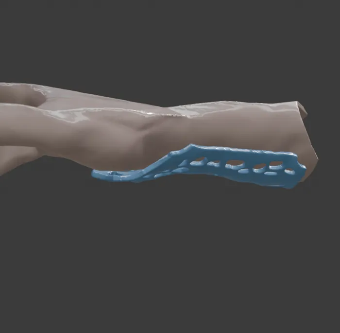
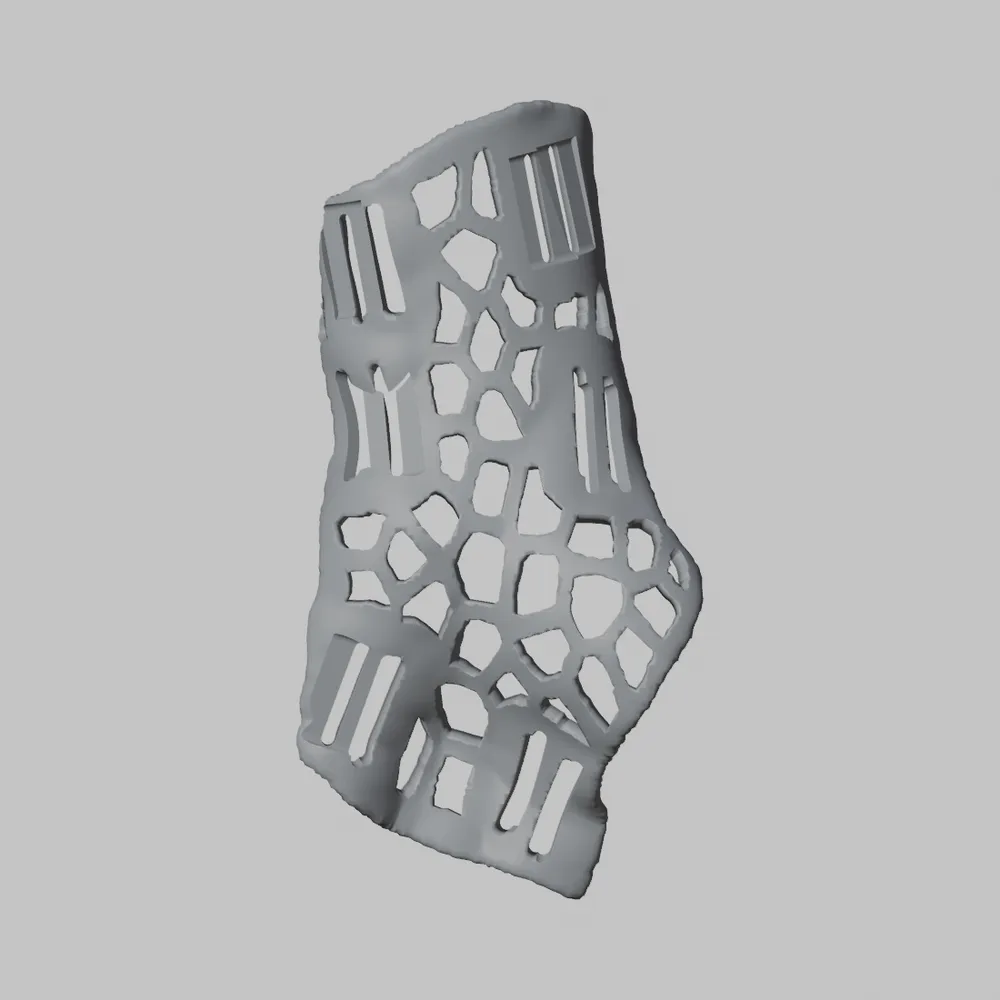
Left: the shell seated on the forearm. Right: the shell with strap slots. Design renders; not a final product.
Orthosis from a scan
Custom knee brace — a two-part shell from a scan
A software pipeline that turns a phone LiDAR scan into a two-part, carbon-reinforced nylon knee-brace shell. The skin-to-shell distance varies by region (the fibular head, epicondyles and the back of the knee each get their own margin), windows open in a gradient Voronoi pattern, and a printed adapter cassette receives an off-the-shelf hinge. The pipeline is verified end to end on synthetic scans; a real scan and a volunteer fitting are next.
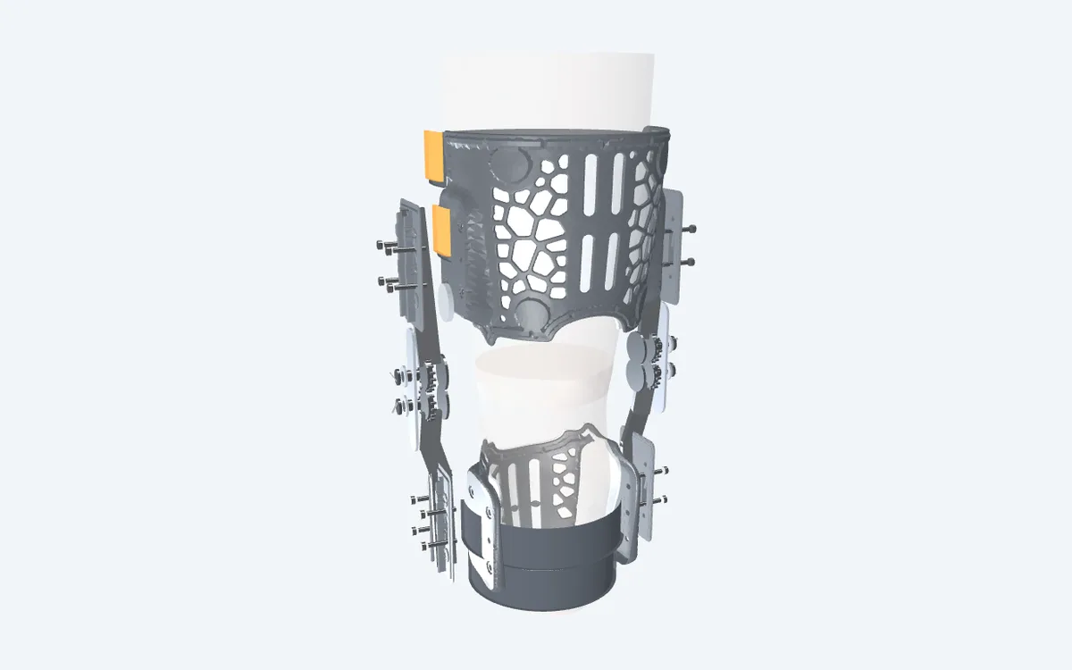
A frame from the full-assembly 3D preview: thigh shell anterior, shank shell posterior, off-the-shelf hinge bars joined through the cassette.
Active orthosis
Active foot-drop orthosis — a tendon-wire design study
A tendon-wire, single-actuator active ankle–foot orthosis design for foot drop: it lifts the foot in swing and releases it in stance. The balance arm that shares load between two wire branches, the passive spring that holds the foot if a wire breaks, and a "silent failure" simulation can all be explored in the 3D preview. The lessons of this study were carried into the actuated AFO design.
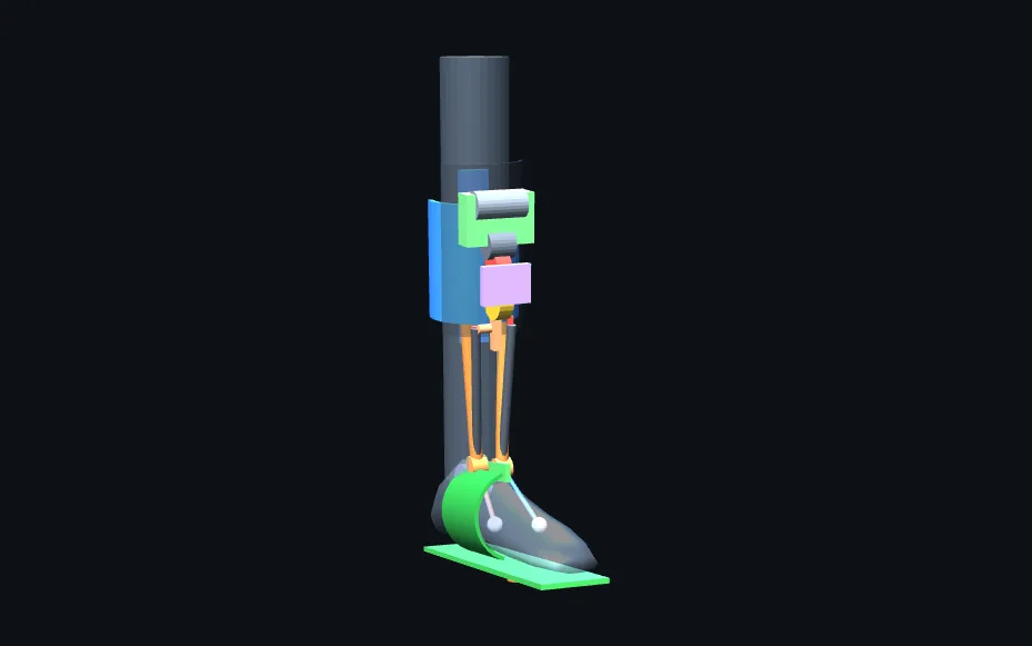
Schematic design preview (about 1 MB, loads on click). Click a part to see its name; the bottom bar plays the gait cycle.
Converting an off-the-shelf brace
Actuated AFO — an actuator in place of the dial
A small actuator replacing the hand-turned dial of an off-the-shelf, dial-adjusted soft ankle brace. Driven by shank angle, it pulls in swing and relaxes in stance; one input, one output. The only 3D-printed part is the actuator seat. Geometry was scaled from product imagery; wire force and pulley torque come from a parametric calculation, and a contact audit runs on every build.
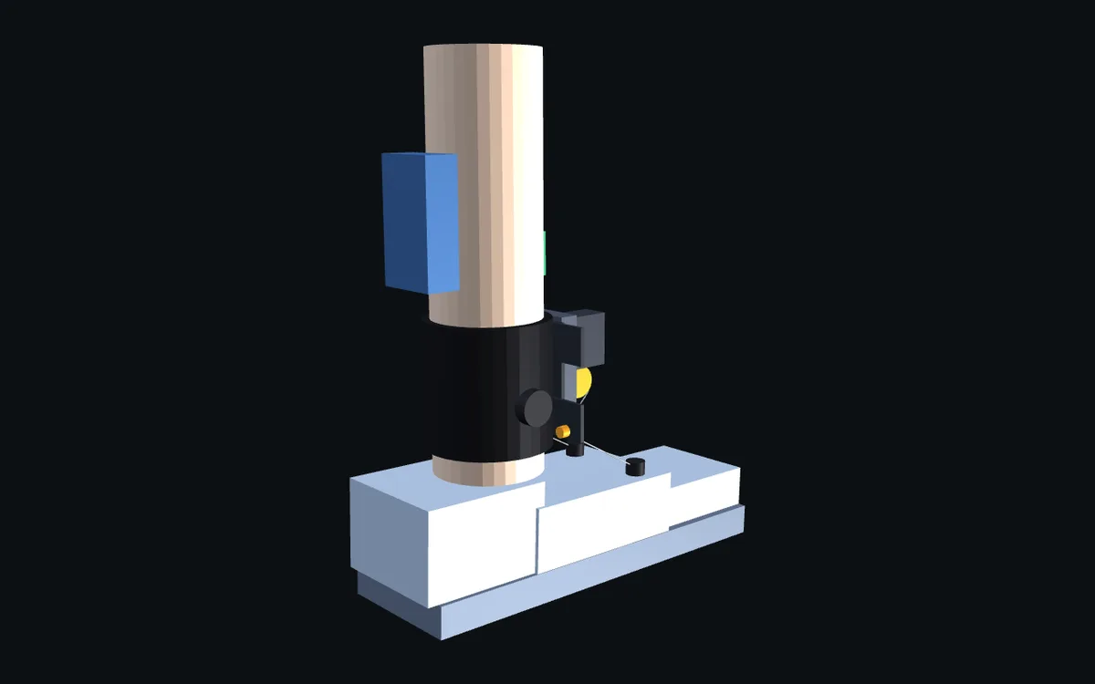
Schematic volume preview, version 0 (about 0.9 MB, loads on click). Watch the actuator pull and release across the gait cycle.
Clinical evaluation and production partnerships
We are open to building the scan–design–print pipeline together with orthosis manufacturers, clinics and clubs.